
- All
- Product Name
- Product Keyword
- Product Model
- Product Summary
- Product Description
- Multi Field Search

Views: 0 Author: Site Editor Publish Time: 2026-07-30 Origin: Site


Achieving sub-micron tolerances and optimal surface finishes relies entirely on the dynamic relationship between the grinding wheel and the workpiece. When you match workpiece and wheel speed correctly, you control the cutting forces and heat generation at the point of contact. Mismatched speeds carry heavy operational costs. You will face thermal damage like grinding burn, severe chatter marks, accelerated wheel wear, and high scrap rates that bottleneck production lines. Solving this requires calculating precise speed ratios in Surface Feet Per Minute (SFPM) or meters per second (m/s). Modern equipment capabilities dictate the accuracy and repeatability of these parameters. Operators must understand how to balance these velocities to maintain wheel geometry and part integrity.
A properly matched speed balances aggressive material removal with the preservation of wheel geometry and part integrity. Success means hitting dimensional tolerances without burning the metal or glazing the abrasive wheel. You must control the relative velocities at the grinding zone. If you run the wheel too fast without adjusting the workpiece rotation, the abrasive grains rub rather than cut. This friction generates massive amounts of heat. Conversely, running the workpiece too fast overloads the individual abrasive grains, causing the wheel to break down prematurely and lose its form.
Wheel speed is calculated in Surface Feet Per Minute (SFPM) or meters per second (m/s). This measures how fast the abrasive grains travel at the outer diameter of the wheel. Workpiece rotational speed is measured in RPM. You must convert this RPM to surface speed to understand the true cutting dynamics. On manual equipment, operators use stepped pulleys to change speeds, which severely limits optimization. A modern CNC cylindrical grinding machine uses servo motors and variable frequency drives for infinite control.
These relative velocities dictate the equivalent chip thickness. This metric defines the size of the micro-chips removed by individual abrasive grains. Thicker chips increase material removal but accelerate wheel wear. Thinner chips improve surface finish but increase the risk of glazing the wheel. To calculate and apply these speeds on the shop floor, follow these specific steps:
The industry starting point for general steel alloys is a 50:1 ratio. This means the wheel surface travels 50 times faster than the workpiece surface. This empirical baseline offers a stable balance of material removal and wheel life for conventional aluminum oxide wheels. You must deviate from this baseline based on the application. Sticking rigidly to 50:1 will cause failures when grinding exotic alloys or using superabrasives.
Workpiece travel across the periphery of the grinding wheel impacts the actual cutting path. In traverse grinding setups, you must synchronize the workpiece RPM with the axial feed rate. The traverse rate per revolution determines how much the wheel overlaps its previous cut. Improper feed-to-speed ratios cause overlapping lead patterns. You will see spiral marks or uneven taper along the workpiece. A faster workpiece RPM requires a proportionally faster traverse rate to maintain consistent wheel overlap.
If you feed too slowly while the workpiece rotates quickly, the wheel dwells in one spot too long, causing localized heat buildup and glazing. If you feed too quickly, the wheel leaves an unground spiral path, often referred to as a "barber pole" finish. The exact overlap depends on the wheel width and the required surface finish.
| Application Type | Recommended Speed Ratio (Wheel:Workpiece) | Typical Traverse Feed per Rev | Expected Surface Finish (Ra) |
|---|---|---|---|
| Aggressive Roughing | 30:1 to 40:1 | 1/2 to 2/3 of wheel width | 63 - 125 µin |
| Standard Grinding (Steel) | 50:1 to 60:1 | 1/4 to 1/3 of wheel width | 32 - 63 µin |
| Fine Finishing | 80:1 to 120:1 | 1/8 to 1/6 of wheel width | 8 - 16 µin |
| Superfinishing (Carbide) | 100:1 to 150:1 | 1/10 to 1/8 of wheel width | 2 - 8 µin |
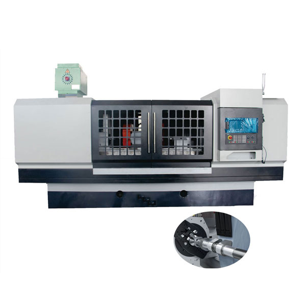
The machine's spindle drive and motor torque translate into stable cutting forces under varying speed ratios. You must evaluate how the machine handles grinding pressure to achieve desired outcomes. When the wheel engages the part, it generates normal forces (pushing the part away) and tangential forces (resisting rotation). Managing these forces requires a deep understanding of how speed ratios affect the physical interaction between the abrasive and the metal.
Workpiece speed, depth of cut, and MRR share a direct correlation. Increasing the workpiece speed or depth of cut increases the MRR. However, higher MRR increases grinding pressure. You need high machine rigidity to prevent deflection under this pressure. Balancing wheel speed and workpiece speed maintains self-sharpening behavior. If the wheel speed is too high relative to the workpiece, the grains dull and glaze. If the workpiece speed is too high, the wheel breaks down prematurely.
To optimize MRR without sacrificing part quality, you must monitor the spindle load meter. A sudden drop in spindle load indicates the wheel has glazed and stopped cutting, requiring an immediate dressing cycle. A steady, high spindle load indicates efficient cutting, provided the part is not suffering from thermal damage. Adjusting the workpiece RPM by just 10% can completely change the cutting action, shifting a glazed wheel back into a self-sharpening state.
The thermodynamics of the grinding zone dictate part quality. Most of the energy consumed during grinding converts into heat. A workpiece rotating too slowly acts as a heat sink. The prolonged contact time leads to surface tempering, tensile residual stresses, or micro-cracking. You must match the wheel speed to the coolant delivery velocity. A fast-spinning wheel creates a boundary layer of air that deflects coolant. Matching the coolant velocity to the wheel speed ensures the fluid breaks this boundary layer and reaches the cutting zone.
Grinding burn is not always visible to the naked eye. Sometimes it manifests as a slight discoloration, but often it requires nital etching to detect the metallurgical changes beneath the surface. To prevent this, ensure your coolant nozzles are aimed precisely at the wheel-workpiece interface. Use high-pressure coolant systems to match the wheel's peripheral speed. If you still experience burn, increase the workpiece RPM to reduce the dwell time of any single point on the part against the wheel.
Different machine architectures handle speed synchronization in distinct ways. You must match the equipment capabilities to your specific application requirements. A setup that works perfectly on a heavy-duty roughing grinder will fail miserably on a high-precision finishing machine. Understanding the mechanical limitations and control features of your specific equipment is non-negotiable for process stability.
Manual grinders rely on stepped pulleys or limited variable speed controls. This restricts your ability to fine-tune speed ratios. Operators must compromise, selecting the closest available speed rather than the optimal one. A CNC control offers infinite, programmable speed adjustments. Constant Surface Speed (CSS) programming is a major advantage of CNC models. As the wheel diameter decreases from dressing, CSS automatically increases the spindle RPM to maintain the exact surface speed. Feed rate override features allow operators to optimize the workpiece rotational speed in real-time based on spark-out observations.
Furthermore, a Cylindrical Grinding Machine equipped with CNC controls can execute complex grinding cycles involving multiple diameters and shoulders in a single setup. The control automatically adjusts the workpiece RPM for each specific diameter to maintain a constant speed ratio across the entire part. This eliminates the need for manual intervention and guarantees consistent surface finishes regardless of the part geometry.
High-RC materials demand specific speed matching requirements. When using an external cylindrical grinder for hardened steels, you often utilize superabrasives like CBN or Diamond wheels. These wheels require significantly higher wheel speeds, often up to 120 m/s. You must adjust the workpiece RPM correspondingly to maintain the optimal chip thickness and prevent thermal damage to the hardened surface.
Grinding hardened tool steels like D2 or M2 requires a delicate balance. If the wheel speed is too low, the CBN grains will pull out of the bond rather than cutting the steel. If the workpiece speed is too high, the aggressive cutting action will generate excessive heat, drawing the temper out of the steel and ruining its hardness. You must use straight oil coolants rather than water-soluble emulsions when running CBN at these extreme speeds to provide adequate lubricity and prevent chemical wear on the abrasive grains.
Grinding long, slender parts presents unique challenges. A shaft grinding machine must control centrifugal forces. You must carefully limit workpiece speed to prevent centrifugal whipping, harmonic vibrations, or mid-span deflection. Operators use steady rests to support the shaft. When you apply steady rests, you must adjust speed ratios to account for the additional friction and support dynamics.
Long shafts are highly susceptible to regenerative chatter. As the part deflects away from the wheel, it creates a high spot. On the next rotation, the wheel hits this high spot, causing a heavier cut and more deflection. This cycle repeats, leaving visible chatter marks. To combat this, you must run the workpiece at a lower RPM to reduce centrifugal forces and use multiple steady rests spaced evenly along the shaft. The grinding wheel must also be dressed with a slightly coarser lead to reduce grinding pressure.
Mechanical failures often mimic or exacerbate speed mismatch issues. You must identify and mitigate these risks to maintain process control. You can calculate the perfect speed ratio, but if your machine bed is twisted or your spindle bearings are failing, the part will still end up in the scrap bin. Rigorous machine maintenance is the foundation of precision grinding.
Perfect speed calculations mean nothing if the machine lacks mechanical alignment. Misaligned workheads and tailstocks cause uneven grinding pressure and roundness errors. Rotational forces and grinding pressure propagate errors throughout the machine bed if the centers are worn. Maintaining true concentricity at high workpiece speeds requires precise setups. Dead-center setups offer superior concentricity compared to live-center setups, as they eliminate bearing runout from the rotation equation.
To ensure proper alignment, you must regularly sweep the workhead and tailstock with a dial indicator. The centers themselves must be inspected for wear and reground or replaced if they show any signs of scoring or grooving. When grinding between centers, the pressure applied by the tailstock quill must be carefully regulated. Too much pressure will bow the part, while too little pressure will allow the part to spin on the centers, destroying the center holes and ruining concentricity.
Chatter marks require a systematic troubleshooting framework. You must distinguish between forced vibrations and self-excited vibrations. Forced vibrations often stem from a wheel out of balance or an incorrect speed ratio. Self-excited vibrations, or regenerative chatter, build up during the cut. Altering the wheel-to-workpiece speed ratio by 5-10% disrupts the harmonic resonance and often eliminates chatter. The dressing lead and dress speed also impact the effective cutting speed ratio and surface finish.
| Defect Type | Visual Appearance | Primary Cause | Speed/Feed Adjustment Solution |
|---|---|---|---|
| Spiraling (Barber Pole) | Helical lines along the part | Traverse feed too fast for workpiece RPM | Increase workpiece RPM or decrease traverse feed rate |
| Chatter (Straight Lines) | Parallel lines across the part axis | Harmonic resonance or wheel imbalance | Change workpiece RPM by 10% to break resonance |
| Grinding Burn | Discoloration (blue/brown) on surface | Excessive heat buildup, glazed wheel | Increase workpiece RPM, dress wheel coarser |
| Glazing | Shiny wheel surface, poor cutting | Wheel speed too high relative to workpiece | Decrease wheel speed or increase workpiece RPM |
Procuring a new machine requires evaluating specific features that guarantee process control and speed synchronization. Legacy equipment simply cannot compete with the dynamic control offered by modern servo systems and advanced software algorithms. When evaluating upgrades, you must look beyond the basic specifications and examine the underlying technology driving the spindles and axes.
High-torque, direct-drive spindles and VFDs are necessary for maintaining exact RPMs under heavy grinding loads. Belt-driven spindles can slip under high MRR, altering the speed ratio. Direct-drive systems eliminate this variable. Dynamic wheel balancing systems integrated into the machine control further stabilize the cutting forces at high speeds. These balancing systems continuously monitor vibration levels and automatically adjust internal counterweights to keep the wheel perfectly balanced, even as it wears down and absorbs coolant.
Modern control architectures allow for in-process gauging. This technology dynamically adjusts speeds and feeds based on real-time dimensional feedback. Investing in machines with thermal stability compensation yields a strong return. These systems maintain tight tolerances across high-volume production runs by adjusting parameters as the machine casting heats up. Sensors embedded in the machine bed monitor temperature fluctuations and feed this data back to the CNC control, which automatically offsets the axes to compensate for thermal expansion.
Matching workpiece and wheel speed is not a static formula. It is a dynamic process dependent on material properties, wheel type, traverse feed rates, and machine rigidity. You must continuously monitor and adjust these parameters to maintain part quality. Relying on outdated manual calculations and legacy equipment limits your ability to achieve sub-micron tolerances consistently.
A: You calculate wheel speed using the formula: SFPM = RPM × Diameter × 0.2618. This sets your baseline parameters. The metric equivalent is m/s = (π × D × n) / 60000, where D is diameter in millimeters and n is RPM.
A: The standard starting point is a 50:1 to 60:1 ratio. This baseline applies to conventional abrasives on standard steels. Specialized setups, like fine finishing or ultra-hard materials, may extend this ratio up to 120:1.
A: The traverse feed rate must synchronize with the workpiece RPM. This ensures proper wheel overlap during the cut. Failing to match these rates causes barber-pole finishes, spiral marks, or premature wheel breakdown.
A: Chatter often results from harmonic resonance caused by incorrect speed ratios. Other common causes include wheel imbalance, lack of machine rigidity, or loose and worn centers in the workhead and tailstock.
A: You maintain concentricity through critical workhead-to-tailstock alignment. You must also ensure appropriate center lubrication and apply correct steady rest pressure to offset the increased centrifugal forces at higher speeds.
A: CNC machines feature programmable Constant Surface Speed (CSS). This automatically adjusts the spindle RPM to compensate for wheel wear. They also utilize precise servo-driven axes to perfectly synchronize rotational speeds with traverse feed rates.


