
- All
- Product Name
- Product Keyword
- Product Model
- Product Summary
- Product Description
- Multi Field Search

Views: 0 Author: Site Editor Publish Time: 2026-07-28 Origin: Site


Internal gear cutting presents a strict physical constraint. You operate within a confined bore where tool drag during the return stroke causes catastrophic tool failure or rejected parts. When a cutter drags against the workpiece on its upward or downward return, the resulting friction destroys the cutting edge and ruins the involute profile. Inadequate cutter clearance directly degrades surface finish, accelerates cutter wear, and increases cycle times, severely impacting overall production profitability.
To solve this, gear manufacturers rely on precise relief mechanisms to pull the cutter away from the material by fractions of a millimeter before the return stroke begins. The evolution of clearance control mechanisms has moved from traditional mechanical cams to advanced servo-driven kinematics. Understanding how an Internal Gear Shaping Machine manages this micro-movement establishes the framework for evaluating which technology aligns with specific production tolerances, part geometries, and volume requirements.
The gear shaping process relies on a continuous reciprocating motion broken down into two distinct phases. We have the cutting stroke and the non-cutting return stroke. During the cutting stroke, the pinion-shaped cutter drives through the workpiece material, shearing away metal to form the gear teeth. Depending on the machine configuration and the part geometry, this cutting stroke can occur on the downward or upward motion. Once the cutter reaches the end of its stroke, it must retract to its starting position. This return stroke does no cutting, but it presents the highest risk to the tool and the workpiece if the cutter remains in contact with the freshly cut metal.
Operators must understand the exact timing of this cycle. If the machine runs at 500 strokes per minute, the window for the cutter to clear the material is measured in milliseconds. A slight delay in the mechanical linkage or servo response means the cutter drags across the hardened steel. This drag generates immense heat, micro-welding chips to the cutting edge and destroying the tool coating.
Relief, commonly referred to as back-off, is the precise radial movement required to separate the cutter from the workpiece during the return stroke. The machine must pull the cutter away by a fraction of a millimeter. We typically set this between 0.3mm and 0.5mm just before the return stroke initiates. This micro-movement prevents the cutting edges from rubbing against the flanks of the newly formed gear teeth.
Without accurate relief, the friction generated during the return stroke generates excessive heat, causes rapid tool wear, and leaves a poor surface finish on the gear profile. The timing of this relief motion must be perfectly synchronized with the stroke crankshaft or servo drive to ensure the cutter is fully clear before reversing direction. In heavy-duty applications cutting 4140 steel, even a 0.1mm error in back-off distance will snap the cutter teeth within the first few passes.
While external gear shaping allows the cutter to move away from the workpiece into open space, internal gear shaping operates under strict spatial limitations. In an internal operation, the cutter is entirely enveloped by the workpiece bore. The relief motion must be tightly controlled because backing the cutter too far away from the active cutting zone risks colliding with the internal diameter on the opposite side of the bore.
This confined environment requires stricter clearance tolerances. The machine must execute a precise, short-travel radial retraction that clears the active teeth without causing secondary interference elsewhere in the internal gear. When setting up a job, machinists must measure the internal diameter and calculate the exact maximum back-off allowable. If the bore is 150mm and the cutter is 100mm, you have limited room to maneuver before the non-cutting side of the tool strikes the opposite wall.
Cutting straight internal splines requires a simple, linear radial retraction. However, cutting helical internal gears introduces complex kinematics. When operating a ring gear shaping machine to produce helical profiles, the clearance motion cannot be a simple straight pull. The cutter must follow a helical path during the back-off, twisting slightly as it retracts to match the helix angle of the gear.
If the machine attempts a straight radial retraction on a helical gear, the sides of the cutter teeth will immediately crash into the angled flanks of the workpiece. Modern machines utilize specialized helical guides or multi-axis interpolation to ensure the cutter twists out of the cut smoothly. Setting up the helical guide requires precise alignment. Operators must verify the lead angle matches the cutter specifications exactly to prevent flank rubbing during the retraction phase.
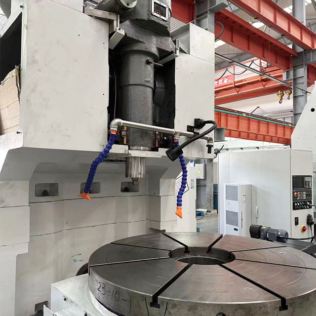
Traditional gear shaping machines manage cutter clearance using a mechanical cam and follower system. This mechanism is physically synchronized with the main stroke crankshaft. As the crankshaft drives the cutter down, the cam profile dictates the position of the cutter spindle or the worktable. At the bottom of the stroke, the cam physically pivots the spindle housing or shifts the table radially to create the necessary back-off distance.
This mechanical linkage ensures the relief timing is inherently tied to the stroke speed. Mechanical cams offer robust reliability and can handle high-speed continuous stroking. However, they possess significant limitations. The relief amount is fixed by the physical geometry of the cam. Changing the back-off distance requires physically swapping cams or performing lengthy mechanical adjustments. Furthermore, mechanical linkages are subject to wear over time. As pins and followers degrade, the relief motion introduces backlash, leading to inconsistent clearance and eventual tool rubbing.
The transition to a CNC internal gear shaper replaces physical cams with servo-driven kinematics. These machines utilize multi-axis interpolation and high-torque motors to electronically control the back-off motion. Instead of relying on a mechanical pivot, the CNC controller commands a servo motor to shift the column, table, or cutter head radially at the exact millisecond the cutting stroke concludes.
Advanced machines integrate hydrostatic or NC guides to execute this motion. Hydrostatic guides float the moving components on a pressurized film of oil, eliminating metal-to-metal friction. This provides highly rigid clearance control, improving accuracy and extending tool life by ensuring the relief distance is identical on every single stroke. The primary advantage of servo-driven relief is programmability. Operators can adjust the relief distance and timing on the fly via the CNC control panel, optimizing the clearance for different materials, varying depth-of-cut passes, or specific tooling requirements without any mechanical teardown.
For low-volume prototyping or repair work, machinists sometimes attempt to cut internal gears using a standard linear shaper equipped with a single-point form tool and an indexing head. This method pushes the technical limits of standard equipment. Because a standard shaper lacks an automated radial relief mechanism synchronized with an indexing rotation, the operator must manually manage tool clearance.
To prevent the single tool tip from rubbing on the return stroke, the machine's clapper box must be heavily modified, locked, or the table must be manually backed off after every single cut. This labor-intensive process is highly prone to human error and yields inconsistent surface finishes. In contrast, a dedicated internal gear shaping machine uses a reciprocating pinion-shaped cutter paired with automated, high-speed radial relief systems. The dedicated machine generates true involute profiles through continuous generating action, vastly outperforming the manual indexing and single-point cutting approach.
| Feature | Mechanical Cam-Driven Relief | CNC Servo-Driven Relief |
|---|---|---|
| Mechanism | Physical cam and follower linked to crankshaft | Multi-axis interpolation via torque motors |
| Adjustability | Fixed; requires mechanical changes | Fully programmable via CNC control |
| Wear & Maintenance | Prone to mechanical wear and backlash over time | Frictionless (with hydrostatic guides), zero wear |
| Helical Capability | Requires physical helical guides | Electronic interpolation handles twisting motion |
| Setup Time | Lengthy manual adjustments | Instantaneous parameter changes |
Proper clearance control begins long before the machine starts stroking. It starts with tool selection. The mathematical relationship between the internal gear's root diameter, the number of teeth, and the maximum allowable diameter of the pinion cutter dictates the success of the operation. If a pinion cutter is too large relative to the internal bore, its physical arc will not fit within the curvature of the internal gear.
Cutter size directly impacts the geometry of the relief motion. A cutter that is too large will lack the necessary physical space to back off from the cutting zone without its non-cutting side striking the opposite wall of the internal bore. Engineers must calculate the maximum permissible cutter diameter to ensure that the programmed relief distance safely clears the internal teeth on the return stroke without causing interference elsewhere. We use specific formulas based on the module and pressure angle to determine the maximum cutter size before interference occurs.
Interference in internal gear shaping typically manifests as trimming. Trimming occurs when the cutter removes material from the flanks of adjacent teeth as it feeds into the cut or as it executes its relief motion. This secondary contact destroys the involute profile and ruins the part. It happens when the geometric path of the cutter teeth intersects with the gear teeth outside the intended cutting zone.
To mitigate this risk, modern machine controls calculate and simulate the exact clearance path before the first chip is made. The CNC software analyzes the cutter diameter, the internal gear geometry, and the required relief distance to ensure the cutter exits the tooth space cleanly. By simulating the kinematics, operators can verify that the back-off motion will not cause secondary contact, allowing them to adjust the cutter size or relief parameters accordingly. If the simulation shows trimming, the operator must select a cutter with fewer teeth.
The precision of the machine's relief mechanism is entirely dependent on the accuracy of the setup. Centering the workpiece over the gear cutter or aligning it perfectly with the machine's rotary table is a critical step. If the internal bore is not perfectly concentric with the axis of rotation, the clearance dynamics become skewed.
Even minor concentricity or axial runout errors lead to asymmetrical clearance. As the machine rotates the part through the generating cycle, the runout causes the internal bore to shift closer to the cutter on one side and further away on the other. This results in the tool rubbing heavily on the tight side of the bore, while having excessive clearance on the loose side. To prevent this, operators must use dial indicators and precision mandrels to sweep the internal bore, ensuring the workpiece axis is perfectly aligned with the machine spindle axis before initiating the cutting cycle. Proper clamping fixtures that prevent distortion during heavy cutting are also mandatory to maintain this alignment.
The precision of the clearance mechanism directly correlates with the resulting surface roughness of the gear teeth and the lifespan of the reciprocating pinion-shaped cutters. When a machine executes a flawless, repeatable back-off motion, the cutting edges remain sharp significantly longer because they are not subjected to the abrasive friction of dragging across hardened material.
When transitioning from older mechanical systems to a modern CNC machine, manufacturers should expect a measurable reduction in tool wear. The elimination of backlash in the relief mechanism ensures the cutter never grazes the workpiece on the return stroke. This precise separation yields superior surface finishes, often eliminating the need for secondary finishing operations like grinding or honing on certain classes of internal gears. You will notice the chips coming off the machine are clean and uniform, rather than torn and discolored from heat buildup.
A fundamental conceptual trade-off in gear shaping involves balancing high strokes-per-minute with the machine's ability to accurately execute the relief motion. At high speeds, the machine has only milliseconds to pull the cutter away from the work, complete the return stroke, and push the cutter back into position before the next downward stroke begins.
Heavy-duty machines must handle the immense inertia of the cutter head or the worktable during these rapid back-off cycles. If the machine lacks sufficient rigidity or servo responsiveness, the rapid direction changes introduce vibration and overshoot. This vibration translates directly into chatter marks on the gear teeth. Evaluating a machine requires analyzing how well its structural castings and guide ways dampen vibration while maintaining exact relief distances at maximum stroke speeds. Look for machines with heavily ribbed cast iron bases to absorb these rapid directional shifts.
Internal gears are frequently located close to shoulders or at the bottom of blind holes, presenting severe clearance challenges. In these applications, the cutter must stop its downward stroke and immediately execute the relief motion within a gap of just a few millimeters to avoid crashing into the bottom of the part.
The clearance mechanism must perform instantaneously at the bottom of the stroke. Mechanical systems often struggle with this due to the physical radius of the cam, which requires a certain amount of over-travel to complete the pivot. CNC servo-driven systems excel here, as they can command an immediate radial retraction the millisecond the Z-axis reaches its programmed depth, making them highly suitable for shaping blind splines and internal gears with minimal undercut clearance. You can program a dwell time at the bottom of the stroke to ensure the relief is fully executed before the upward return begins.
Internal gear shaping traps chips inside the bore. Inadequate clearance combined with poor chip evacuation leads to chip recutting. When chips are not flushed away, they get dragged back into the cutting zone during the return stroke or the subsequent cutting stroke. Recutting hardened chips instantly chips the cutter edges and scores the surface finish of the internal gear.
To mitigate this, manufacturers must evaluate machines equipped with integrated high-pressure coolant systems. The coolant delivery must be synchronized with the relief stroke, blasting fluid directly into the tooth space the moment the cutter backs off. This high-pressure flush clears the chips from the constrained bore before the cutter re-engages the material. We recommend a minimum coolant pressure of 300 PSI directed through adjustable nozzles aimed precisely at the cutting interface.
The radial force exerted during the cutting stroke is substantial. If the machine structure or the cutter spindle lacks rigidity, this cutting force causes deflection. The spindle bends slightly away from the cut. When the stroke finishes and the cutting force drops to zero, the spindle springs back to its natural position.
This spring-back can negate the programmed clearance on the return stroke. If the machine is programmed for a 0.3mm relief, but the spindle deflects 0.2mm during the cut and springs back, the actual clearance is reduced to a dangerous 0.1mm, risking tool drag. Specifying machines with oversized hydrostatic bearings, robust column designs, and thick cutter spindles is necessary to maintain absolute rigidity under heavy cutting loads, ensuring the programmed relief matches the actual physical clearance.
| Symptom | Potential Cause | Corrective Action |
|---|---|---|
| Chatter marks on gear flanks | Vibration during relief stroke | Reduce stroke speed or check guide rigidity |
| Rapid cutter edge chipping | Chip recutting in the bore | Increase coolant pressure and adjust nozzle aim |
| Asymmetrical tool wear | Workpiece runout or poor centering | Re-indicate the bore and adjust clamping fixtures |
| Trimming on adjacent teeth | Cutter diameter too large for bore | Select a cutter with fewer teeth |
Precise cutter clearance remains the defining factor in internal gear shaping success. Without accurate back-off on the return stroke, tool life plummets, and part quality degrades. The shift toward CNC-driven relief mechanisms offers superior flexibility, allowing operators to program exact clearance paths that adapt to complex helical geometries and tight blind-hole constraints, far outperforming traditional mechanical cams.
Procurement and engineering teams evaluating new equipment should prioritize machines based on guide rigidity, the responsiveness of the programmable relief capabilities, and the specific geometric constraints of their workpieces. A machine cutting through-hole ring gears requires different stroke capabilities than one cutting blind internal splines near a shoulder.
To ensure successful implementation, take the following next steps:
A: Cutter clearance prevents the tool from dragging against the workpiece during the non-cutting return stroke. This micro-retraction eliminates friction, preserves the sharp cutting edges of the tool, prevents chipping, and ensures a clean, accurate surface finish on the gear teeth.
A: It uses synchronized servo motors and advanced NC guides to electronically dictate the back-off motion. The CNC controller commands the motors to dynamically pull the cutter spindle or the worktable away from the cut by a precise, programmable distance at the end of each cutting stroke.
A: Interference, or trimming, occurs when the pinion cutter is too large relative to the internal gear's root diameter and tooth count. The physical arc of the oversized cutter intersects with the flanks of adjacent internal teeth during the feed or relief motion, destroying the gear profile.
A: While single-point tools can be used with custom clapper-box setups and indexing heads on standard shapers for prototyping, true involute internal production gears require a dedicated gear shaping machine. Dedicated machines provide the precise continuous indexing and automatic radial relief mechanisms necessary for accurate, high-volume production.
A: Runout or centering errors create asymmetrical clearance. As the part rotates, the bore shifts closer to the cutter on one side and further away on the other. This uneven distance causes the tool to rub heavily on the tight side, leading to localized cutter damage and profile distortion.
A: Preventing chip recutting requires a combination of precise cutter back-off, optimized stroke timing, and targeted high-pressure coolant. The coolant system must flush the chips out of the confined bore at the exact moment the cutter relieves, ensuring a clean tooth space for the next stroke.
A: Hydrostatic guides float moving components on a pressurized film of oil, eliminating metal-to-metal mechanical friction. This results in zero wear over time, higher structural rigidity, and highly repeatable clearance motions, ensuring consistent relief distances and extended tool life.


