
- All
- Product Name
- Product Keyword
- Product Model
- Product Summary
- Product Description
- Multi Field Search

Views: 0 Author: Site Editor Publish Time: 2026-07-31 Origin: Site


In broaching operations, the feed rate is not controlled by the machine operator; it is permanently engineered into the geometry of the tool itself. Specifying an incorrect Rise Per Tooth (RPT) leads to compounding failures—excessive machine load, catastrophic tool breakage, unacceptable surface finishes, and high scrap rates. Understanding the precise mechanical relationship between RPT, cutting force, and material behavior is mandatory for engineers evaluating and procuring the correct broaching cutter for high-volume or high-precision manufacturing. When you get the RPT wrong, you either stall the ram, snap the tool, or tear the workpiece material beyond repair. We need to look at exactly how chip thickness dictates load and why staging the cut from roughing to finishing is the only way to hold tight tolerances on the shop floor.
Rise Per Tooth (RPT) is the dimensional difference in height or radius between successive teeth on the cutter. You will frequently see it referred to in technical manuals and tooling prints as the "step per tooth" or "feed per tooth." RPT directly determines the cross-sectional area of the chip generated by each tooth. When a tooth enters the cut, it shears off a layer of material exactly equal to its RPT. This volume of metal must curl and pack into the chip gullet ahead of the tooth. If the RPT is too large for the gullet volume, the chip packs solid, the cutting force spikes, and the tool breaks.
On the shop floor, chip formation tells you everything about your RPT. A properly sized RPT produces a tightly curled chip that falls away easily at the end of the stroke. If the chips are straight, fractured, or jammed into the gullets, the relationship between the RPT, the face angle, and the gullet radius is fundamentally flawed.
A properly designed broach features a distinct progression of teeth. You do not use the same RPT across the entire length of the tool. The geometry is staged to balance heavy material removal with final dimensional accuracy.
This staged geometry eliminates the need for multiple tool passes. You get a finished part in a single stroke, driving operational efficiency and ensuring dimensional accuracy without secondary operations.
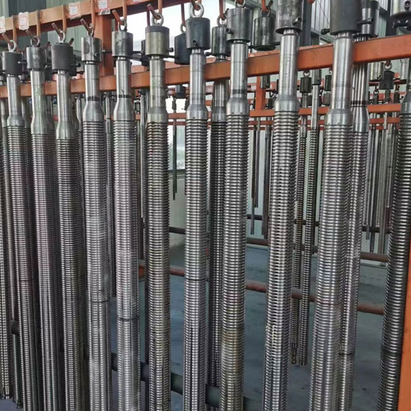
The broaching load is a direct, linear function of the RPT. The basic formula for calculating the required load is: Load = (Number of teeth engaged) × (RPT) × (Width of cut) × (Specific cutting force of the material). When you increase the RPT, you increase the chip thickness, which proportionally increases the cutting force required to shear the material.
Engineers must calculate the maximum number of teeth engaged in the workpiece at any given moment during the stroke. If you have a long part and a short pitch between teeth, you might have ten teeth cutting simultaneously. Multiply that by an aggressive RPT, and your tonnage requirements will skyrocket.
Subjecting tool materials like PM-M4 or M2 High-Speed Steel to excessively high RPT pushes them toward their mechanical limits. The primary implementation risk is exceeding the tensile strength of the broach neck (the weakest point of a pull broach) or surpassing the maximum tonnage capacity of the machine ram.
When you overload the tool, it deflects. In internal broaching, this deflection causes the tool to drift off-center, ruining the concentricity of the bore. If the load exceeds the ultimate tensile strength of the high-speed steel, the broach will snap inside the part. Extracting a broken broach from a hardened workpiece is a nightmare that usually results in scrapping both the tool and the part.
A high-risk scenario occurs when a single overloaded tooth chips or breaks. When tooth number five breaks, it leaves its designated material behind. Tooth number six now hits the workpiece and is forced to take a double-RPT workload. Because tooth six was not designed for double the chip load, it breaks immediately.
This failure transfers a triple load to tooth seven, initiating a rapid cascade effect. A single damaged tooth compromises the size, surface finish, and dimensional stability of all subsequent passes, often destroying the entire tool in a fraction of a second.
Before approving a custom broach design with an aggressive RPT, you must audit your existing machine capabilities. Do not guess on tonnage.
An overly aggressive RPT causes the material to fracture ahead of the cutting edge rather than shear cleanly. This leaves a torn, pitted, or flaked surface finish on the workpiece. You will physically see the tear marks dragging along the axis of the cut.
Additionally, when cutting forces exceed the rigidity of the setup, harmonic chatter occurs. The tool begins to bounce against the workpiece, leaving a distinct washboard pattern on the surface. Chatter degrades the surface quality, destroys tolerances, and accelerates wear on the cutting edges.
You cannot simply drop the RPT to zero to get a better finish. If the RPT is less than the cutting edge radius of the tool, the tooth will rub against the workpiece rather than bite into it. This generates massive amounts of friction and heat.
In materials like stainless steel or high-nickel alloys, this rubbing causes severe work hardening. The surface of the part becomes harder than the base material, destroying the subsequent teeth that try to cut it. The heat also causes material adhesion, where microscopic bits of the workpiece weld themselves to the tooth flanks, creating a Built-Up Edge (BUE). BUE ruins the surface finish and alters the effective geometry of the tool.
The final teeth on a broach are engineered solely to size the part and burnish the surface. With an RPT of 0.01 to 0.04 mm, they neutralize the rough finish left by preceding teeth. These teeth often have a slightly different face angle and a larger land to stabilize the tool and iron out any microscopic peaks left in the bore.
Spline broaching presents unique RPT challenges because multiple teeth engage simultaneously across a large internal circumference. When pulling an internal spline broach tool, the total cutting perimeter is massive. Staggered tooth designs (where alternate teeth cut the major diameter and the involute form) are utilized to break up the chip and reduce the total tonnage.
The RPT profile must prevent chip packing in internal blind or through-holes. If the chips cannot evacuate, they will score the freshly cut splines as the tool exits the part.
For keyway cutting, the RPT distribution focuses on balancing heavy material removal with maintaining strict perpendicularity. A keyway broaching cutter is essentially a single-point tool stretched out linearly. If the RPT is too high, the asymmetrical cutting force will push the tool away from the cut, causing the keyway to drift out of tolerance or taper from top to bottom.
Tool support dictates your RPT constraints. Surface broaches can handle much higher RPTs because they are bolted to massive, rigid backing fixtures that absorb the cutting forces. Internal broaches are limited by their own cross-sectional strength. They must survive the tensile load of being pulled through the part without snapping.
| Broach Type | Typical RPT Capability | Primary Mechanical Constraint | Common Failure Mode if Overloaded |
|---|---|---|---|
| Surface Broach | High (0.10 - 0.25 mm) | Fixture Rigidity & Machine Ram | Chatter / Insert Breakage |
| Internal Spline Broach | Moderate (0.05 - 0.15 mm) | Tool Cross-Sectional Tensile Strength | Neck Fracture / Drift |
| Keyway Broach | Moderate (0.05 - 0.12 mm) | Deflection / Perpendicularity | Tapered Cut / Horn Breakage |
Soft, gummy materials tend to adhere to the cutter under incorrect RPT profiles. This adhesion occurs directly on the tooth flanks and lands, resulting in catastrophic tearing and rapid loss of dimensional control. The material does not want to shear; it wants to smear.
To mitigate this, you must specify larger RPTs to force the tool to take a definitive bite. You also need highly polished chip gullets and a steeper hook angle to ensure clean shearing and prevent built-up edge. If you use a shallow RPT on soft aluminum, you will just gall the surface.
Machining hardened alloys (like 4140 pre-hard or titanium) requires lower RPTs to manage extreme cutting forces and heat generation. The material resists shearing, so taking a large bite will stall the machine or chip the tool.
The trade-off involves balancing the need for a lower RPT against the physical length of the tool. If you drop the RPT to protect the cutting edges, you need more teeth to remove the same amount of material. More teeth mean a longer broach tool, which requires a machine with a longer stroke. You cannot cheat this math.
Inspecting a used cutter under magnification helps determine if RPT is the root cause of failure. You need to look at specific wear patterns.
Broaches are re-sharpened by grinding the face of the tooth. Repeated sharpening alters the face angle and reduces the gullet depth. This inadvertently affects chip flow and effective cutting dynamics, even if the RPT remains constant.
As the gullet gets shallower, it can hold less chip volume. If you maintain the original RPT on a heavily sharpened tool, the chips will pack and break the broach. Establishing a strict lifecycle and re-sharpening schedule is essential to maintain surface finish consistency over high-volume production runs.
A: There is no single standard, as it depends on the material and tool type. Generally, roughing teeth use 0.05 mm to 0.2 mm per tooth, while finishing teeth use 0.01 mm to 0.04 mm to ensure proper sizing and surface finish.
A: A higher rise per tooth generates thicker, larger chips. These chips require larger gullet volumes between the teeth to curl properly. If the RPT exceeds the gullet capacity, the chips pack solid, causing tool breakage.
A: No. The feed rate is permanently engineered into the tool's geometry via the rise per tooth. You cannot adjust the chip load on the machine; you can only adjust the cutting speed (ram velocity).
A: A torn finish usually results from an overly aggressive rise per tooth causing the material to fracture rather than shear. It can also be caused by material adhesion (built-up edge) on the cutting edges due to poor coolant application.
A: Pulling force is calculated by multiplying the maximum number of simultaneously engaged teeth, the rise per tooth, the width of the cut, and the material's specific cutting force. This ensures you do not exceed machine tonnage.
A: If the rise per tooth is smaller than the cutting edge radius, the tool rubs instead of cutting. This causes rapid edge wear, massive heat generation, and severe work hardening of the workpiece material.
A: Yes, these terms are used interchangeably in the machining industry to describe the dimensional difference in height or radius between successive teeth on a broach.


