
- All
- Product Name
- Product Keyword
- Product Model
- Product Summary
- Product Description
- Multi Field Search

Views: 0 Author: Site Editor Publish Time: 2026-07-28 Origin: Site


In continuous, large-volume gear cutting, thermal stability is the primary bottleneck for maintaining AGMA/DIN quality standards over extended cycle times. Friction from the cutting interface, spindle bearings, and hydraulics introduces severe thermal gradients. This causes thermal expansion in both the machine structure and the workpiece, leading to profile deviations, lead errors, and costly scrap in large-diameter applications. Mitigating these variables requires moving beyond basic environmental controls. Evaluating a modern heavy duty gear hobbing machine requires a strict analysis of its structural thermodynamics, active cooling systems, and real-time software compensation capabilities. Machinists and production engineers must understand how heat flows through the casting, how the CNC interprets sensor data, and how physical setup choices either amplify or suppress thermal drift during multi-hour cutting cycles.
Defining acceptable thermal drift limits establishes the baseline for large-scale gear manufacturing. Heat compromises these tolerances by physically altering the dimensions of the gear blank, the cutting tool, and the machine axes. When cutting cycles last several hours, even a minor temperature shift pushes a large-diameter gear out of acceptable AGMA or DIN limits. Operators must control these thermal shifts to prevent cumulative pitch errors. A temperature rise of just a few degrees in a steel workpiece with a two-meter diameter results in measurable expansion. This expansion forces the hob to cut deeper into the material than programmed. Once the part finishes and cools down to room temperature, the gear teeth shrink back, leaving an undersized profile and excessive backlash.
Thermal expansion represents the physical tendency of gear components to expand in size, surface area, and total volume as temperatures rise. During the cutting process, metal absorbs heat and physically grows. This volumetric expansion alters designed clearances. It leads directly to mechanical misalignment, interference, or severe cumulative pitch errors during continuous operation. Steel expands at a predictable rate, typically around 12 micrometers per meter per degree Celsius. In large module applications, this coefficient of thermal expansion translates into massive dimensional shifts. If the machine column leans forward due to uneven heating from the spindle motor, the hob angle changes relative to the workpiece axis. This angular shift introduces lead errors that cannot be corrected during the finishing pass.
Heat enters the machining process through several distinct pathways. Understanding these zones allows engineers to implement targeted cooling strategies rather than relying on generalized shop floor air conditioning.
Thermal expansion maps directly to specific gear defects. Uneven heating warps large workpieces during multi-hour cutting cycles on a large module gear cutting machine. As the gear blank expands, the tool cuts deeper than intended. When the part cools and shrinks, the resulting gear teeth exhibit altered clearances, severe misalignment, pitch errors, and lead distortion. The table below outlines the direct correlation between specific heat sources and the resulting geometric failures on the finished gear.
| Heat Source Location | Physical Thermal Effect | Resulting Gear Defect | Severity Level |
|---|---|---|---|
| Cutting Interface | Workpiece radial expansion | Profile deviation, altered root diameter | High |
| Main Spindle Bearings | Tool arbor axial elongation | Lead distortion, shifting contact pattern | High |
| Hydraulic Power Units | Asymmetrical bed warping | Mechanical misalignment, taper errors | Medium |
| Hydrostatic Guideways | Column tilt or twist | Cumulative pitch errors, runout | Medium |
| Ambient Shop Air | Global machine expansion | Inconsistent sizing across batches | Low to Medium |
Evaluating the physical construction of the machine comes before looking at add-on technologies. Traditional cast iron features high thermal inertia, meaning it holds onto heat and expands unevenly. Conversely, mineral cast or polymer concrete beds offer superior thermal stability and vibration damping. Polymer concrete absorbs heat much slower than cast iron, creating a massive thermal buffer against rapid temperature spikes. Symmetrical machine design ensures that when expansion occurs, it happens predictably and uniformly across the entire structure. A thermally symmetrical column will expand straight up rather than bowing to one side, keeping the hob perfectly parallel to the workpiece axis. This predictable linear expansion is much easier for the CNC to compensate for than complex twisting motions.
Precise spindle synchronization and minimal backlash in feed mechanisms lower cutting resistance. Minimizing mechanical friction directly reduces the baseline heat generation of the equipment. Structural support rigidity prevents structural deflection under heavy cutting loads. Deflection introduces localized heat spikes by forcing the tool to rub rather than shear the metal cleanly. When a machine lacks rigidity, the cutting forces push the hob away from the blank. The servo motors then draw more current to force the tool back into position, generating excess electrical heat. Upgrading to direct-drive torque motors eliminates gearboxes and belts, removing several mechanical friction points from the kinematic chain. This reduces the overall thermal load on the machine head.
To verify the kinematic precision and structural integrity of a new machine installation, operators should follow a strict mechanical audit process before running production parts.
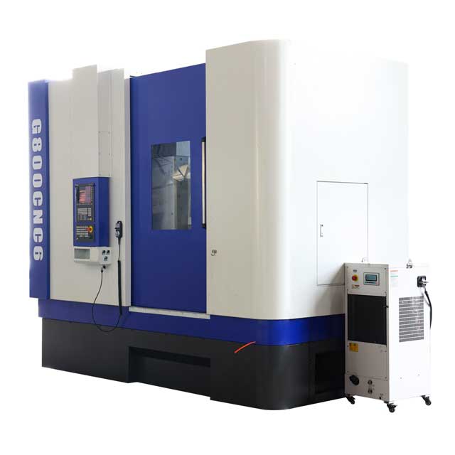
Assessing OEM cooling configurations requires looking at passive systems first. Passive thermal controls include physical heat sinks and strategic ventilation paths. Physical isolation of heat-generating components is vital. Moving electrical cabinets and hydraulic tanks away from the machine bed prevents radiant heat from warping the main casting. Many manufacturers now mount the main electrical enclosure on a separate floor stand, connected only by flexible cable tracks. This completely decouples the heat generated by the servo drives and transformers from the precision machine base. Additionally, designing the machine enclosure with steep sloped guarding ensures that hot chips fall immediately into the conveyor rather than resting on the machine bed and transferring heat into the casting.
Active cooling is mandatory for heavy-duty applications. Chiller units for cutting fluids and lubricating oils remove heat directly from the source. Water-cooled torque motors, temperature-controlled hydrostatic guides, and spindle cooling jackets maintain strict temperature bands. The ultimate goal is homogenizing temperatures and limiting thermal gradients across all critical axes of the large diameter CNC gear hobber. A high-performance active cooling system will circulate refrigerated fluid through a labyrinth of channels cast directly into the spindle housing. This pulls heat away from the bearings before it can travel down the arbor. The hydrostatic oil must also pass through a dedicated heat exchanger to maintain a constant temperature, usually within 0.5 degrees Celsius of the ambient shop environment.
When evaluating the active cooling infrastructure of a prospective machine purchase, engineers should demand specific performance metrics from the manufacturer.
Assessing the digital capabilities of modern equipment reveals how software bridges the physical gap. Strategic placement of thermal sensors across the machine casting, spindles, and ambient environment provides continuous data. These sensors feed real-time temperature fluctuations directly into the machine controller. A typical setup includes PT100 temperature probes embedded in the main column, the bed, the spindle housing, and the cutting fluid tank. By monitoring the temperature differential between the front and rear of the column, the CNC can calculate the exact amount of thermal bow occurring in the structure. This data forms the foundation for all subsequent software compensation routines.
Modern CNC systems use thermal error mapping to predict distortion before it ruins a part. Advanced software frameworks, such as the CNN-DAE (Convolutional Neural Network - Deep Autoencoder) integrated structure, model non-linear thermal behaviors. The controller dynamically offsets the X, Y, and Z axes in real-time. This algorithmic compensation corrects for micro-expansions during continuous large-volume cutting. Instead of waiting for a post-process inspection to reveal a size error, the machine proactively shifts the tool path by a few microns every minute to counteract the physical growth of the casting. This requires immense processing power and a highly accurate mathematical model of the machine's specific thermodynamic properties.
The implementation of these predictive models follows a specific sequence during the machine commissioning phase.
Dry hobbing offers distinct environmental and fluid disposal benefits. However, the thermal risk is severe. Dry cutting relies heavily on specialized carbide tools and rapid chip evacuation to carry heat away from the workpiece. Dry hobbing requires superior machine-side thermal compensation, such as CNN-DAE mapping, to manage the complete lack of liquid cooling. When cutting dry, the chips must absorb at least eighty percent of the generated heat. If the chips fail to break cleanly or if they accumulate in the cutting zone, that heat transfers immediately into the gear blank. This makes dry hobbing highly dependent on aggressive cutting parameters. Operators must push the tool hard enough to eject the chips forcefully, which requires a machine with exceptional structural rigidity and high-torque spindles.
High-volume, temperature-controlled cutting oil acts as a massive thermal stabilizer for both the tool and the large gear blank. Wet hobbing flushes chips away instantly and prevents localized heat buildup. Operators must manage the trade-offs, which include fluid management logistics, mist extraction requirements, and thermal shock risks if coolant delivery becomes inconsistent during the cut. The cutting oil must be delivered at high pressure directly into the root of the cut to break the vapor barrier generated by the extreme heat. If the coolant nozzles are misaligned, the tool will experience rapid heating and cooling cycles, leading to premature edge failure through thermal cracking. Maintaining the cutting oil at a stable temperature is just as critical as maintaining the machine casting temperature.
| Process Characteristic | Wet Hobbing | Dry Hobbing |
|---|---|---|
| Primary Heat Sink | Cutting oil and chips | Chips only |
| Tooling Requirements | Standard HSS or coated carbide | High-performance coated carbide (TiAlN) |
| Machine Rigidity Needs | High | Extreme |
| Thermal Shock Risk | High (if coolant flow is interrupted) | Low |
| Workpiece Temperature Stability | Excellent (oil acts as a thermal bath) | Poor (requires aggressive CNC compensation) |
Thermal control strategies often fail right on the shop floor due to poor setup. Over-clamping thin-webbed gears exacerbates thermal warping by introducing internal stress. Operators must verify OD, face runout to bore, and squareness before the part enters the hobbing cell. Documenting and controlling Arbor TIR (Total Indicator Runout) eliminates runout-induced friction. If a gear blank is clamped with excessive force, the metal distorts elastically. As the cutting process heats the part, these internal stresses release unpredictably, causing the gear to warp out of tolerance. Using hydraulic expansion arbors or precision diaphragm chucks provides even, repeatable clamping pressure that minimizes induced stress. Furthermore, ensuring the mating surfaces of the fixture are perfectly clean prevents microscopic chips from throwing the blank out of square.
Placing high-precision machinery in facilities with severe diurnal temperature swings guarantees failure. Direct sunlight exposure on a machine casting causes immediate, asymmetrical thermal expansion. Facilities require climate-controlled foundations and dedicated enclosures to isolate the machine from ambient shop floor variations. A heavy-duty machine should sit on an isolated concrete pad, separated from the main shop floor by an expansion joint. This prevents vibrations from nearby stamping presses or forklifts from interfering with the cut, but it also provides a stable thermal mass beneath the machine. The ambient air temperature around the machine should be controlled to within plus or minus one degree Celsius. High-velocity HVAC vents must not blow directly onto the machine casting, as this creates localized cold spots that warp the column.
Controlling thermal deformation requires a thermally stable machine architecture, active cooling, and intelligent CNC compensation. Buyers must prioritize machines based on verifiable thermal mapping data, the availability of active spindle cooling, and the rigidity of the machine base. Implementing these systems ensures that large-diameter gears meet strict quality standards regardless of cycle time or ambient shop conditions.
A: Temperature increases cause the workpiece and machine axes to expand in size, area, and volume. This alters design clearances and results in profile, pitch, and lead deviations. The tool cuts deeper into the expanded metal, leaving an undersized gear once the part cools and shrinks back to room temperature.
A: It is the use of strategically placed sensors and algorithms to model heat distribution. The CNC uses this data to dynamically adjust the machine's axes, offsetting physical expansion in real-time. This prevents dimensional drift during long cutting cycles without requiring manual operator intervention.
A: Yes, but it requires highly optimized chip evacuation, advanced tool coatings, and robust machine-side thermal compensation. The chips must carry the heat away from the blank. If chips accumulate, the heat transfers to the workpiece, causing severe thermal distortion.
A: Poor synchronization increases cutting forces, vibration, and mechanical friction. This exponentially increases localized heat generation at the cutting zone. Precise synchronization ensures the tool shears the metal cleanly rather than rubbing against it, significantly lowering the baseline thermal load.
A: Materials with lower thermal conductivity and higher thermal mass, such as polymer concrete, resist rapid temperature fluctuations better than traditional cast iron. They absorb heat slowly, creating a thermal buffer that prevents sudden, unpredictable warping of the machine structure during operation.
A: Excessive clamping force or poor arbor alignment creates internal stresses and localized friction. As the workpiece heats up during the cut, these stresses release unpredictably, compounding structural warping. Proper setup ensures the part remains stable as cutting temperatures rise.


