
- All
- Product Name
- Product Keyword
- Product Model
- Product Summary
- Product Description
- Multi Field Search

Views: 0 Author: Site Editor Publish Time: 2026-07-29 Origin: Site


High-mix, low-volume gear manufacturing demands a difficult compromise between micron-level precision and rapid changeover capabilities. Traditional generating grinding excels in mass production but introduces prohibitive tooling costs and setup bottlenecks when applied to varied batches, custom profiles, or specialized geometries like double helical or large-diameter gears. For facilities managing diverse part families, investing in a modern Profile Gear Grinding Machine shifts the production bottleneck from setup and tooling to optimized machine utilization. You must evaluate the equipment against strict flexibility, kinematic capability, and thermal stability criteria to ensure it meets the rigorous demands of modern job shops. Shifting away from dedicated hobs to flexible wheel profiles allows operators to tackle complex root geometries and asymmetrical profiles without waiting weeks for custom tooling to arrive.
Defining the threshold where high-mix production renders generating grinding economically unviable requires looking at custom hob costs and changeover downtime. When a shop runs batches of five to fifty gears, the time spent dialing in a continuous generating grinder often exceeds the actual cycle time. Machining tooth flanks gap-by-gap with profiled tools allows for infinite profile variations using standard, easily dressable abrasive wheels. You can switch from a standard spur gear to a heavily modified helical gear simply by running a new dressing cycle and changing the part program.
A direct evaluation of continuous generating grinding versus gap-after-gap profile grinding reveals stark contrasts in high-mix variables. Tooling amortization thresholds for generating hobs require thousands of parts to break even. Lead times for these custom tools can stretch into months. In contrast, a profile gear grinding machine uses standard vitrified wheels that you can profile on the machine in minutes. Setup-to-run ratios for batch sizes under 50 units heavily favor the profile method. Kinematic limitations also restrict generating grinders when processing restricted-clearance geometries, whereas profile grinders excel at navigating tight shoulders.
| Production Variable | Continuous Generating Grinding | Gap-after-Gap Profile Grinding |
|---|---|---|
| Tooling Inventory | Extensive custom hobs required per profile | Minimal standard wheels dressed on-machine |
| Setup Time (Small Batch) | 2 to 4 hours for mechanical dial-in | 15 to 30 minutes via parametric software |
| Clearance Capabilities | Poor; requires large runout zones | Excellent; ideal for double helical and tight shoulders |
| Geometric Flexibility | Fixed to the hob's specific design | Infinite variations via CNC dressing |
| Thermal Control | Continuous heat distribution | Requires targeted high-pressure coolant |
Establishing baseline metrics for a successful machine integration involves tracking specific shop floor data. You should aim to reduce changeover time by at least 40 percent within the first quarter of implementation. Eliminating the need for outsourced custom tooling entirely is a realistic goal for most job shops. Maintaining DIN/ISO quality class 2-4 across varied batches proves the machine's capability. Operators must document first-part inspection times to ensure the automated probing routines function correctly.
The transition requires a shift in how production planners schedule jobs. Instead of grouping parts by identical profiles to save on hob changes, planners can group parts by base material or wheel grit requirements. This flexibility keeps the spindle turning and maximizes overall equipment effectiveness. We see shops taking on emergency repair work for mining or marine gears simply because they no longer have to wait for a custom tool to be manufactured.
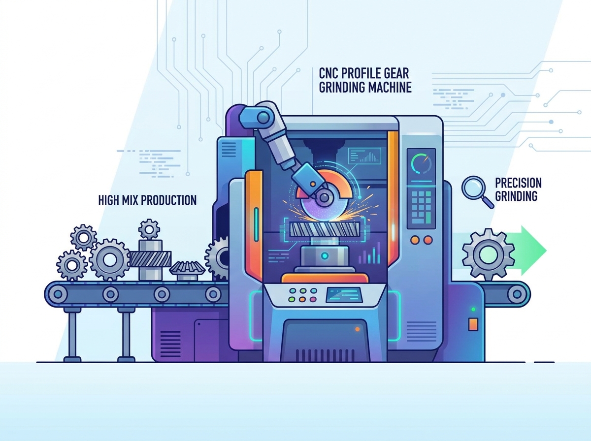
Evaluating the necessity of a 5-axis configuration reveals its importance for complex root geometries, topological modifications, and twist-free tooth flank grinding. Standard 3-axis machines cannot interpolate the complex curves required for modern aerospace or wind turbine gears. The simultaneous movement of X, Y, Z, A, and C axes allows the grinding wheel to follow the exact mathematical curve of the modified involute. This prevents the unwanted twist that often occurs when grinding heavily crowned helical gears.
The role of a tangential axis provides critical tool clearance and precision for double helical gears and gears with restrictive shoulders. By shifting the wheel tangentially, the machine can utilize different sections of the abrasive, extending wheel life and maintaining sharp cutting edges. This axis also allows for the precise positioning of the wheel when navigating the narrow gap between double helical gear tracks. Without a robust tangential axis, machining these components requires splitting the gear into two pieces, which compromises structural integrity.
Assessing rotary table direct-drive technology is mandatory for positioning accuracy, thermal dissipation, and backlash elimination under heavy workpiece loads. Traditional worm gear drives introduce mechanical backlash that degrades tooth spacing accuracy over time. Direct-drive torque motors eliminate this mechanical linkage. They provide instantaneous response to CNC commands and maintain sub-arc-second positioning accuracy. You must ensure the table includes adequate liquid cooling channels to dissipate the heat generated by the torque motor during rapid indexing.
Comparing single-ribbed versus multi-ribbed grinding wheels depends heavily on batch size, module range, and material removal rates. Single-ribbed wheels offer the ultimate flexibility for high-mix environments. They can grind a massive range of modules simply by changing the CNC dressing program. Multi-ribbed wheels increase material removal rates for slightly larger batches but require more complex dressing routines and limit the maximum module size based on the wheel width.
Abrasive selection for high-mix environments requires evaluating the trade-offs between dressable vitrified bonded wheels and electroplated CBN wheels. Vitrified aluminum oxide or ceramic corundum wheels provide maximum geometric flexibility. You can dress them into any shape required. Electroplated Cubic Boron Nitride wheels offer high-speed, dressing-free runs on standardized profiles. However, once a CBN wheel wears out or the profile requirement changes, you must send it out for stripping and replating. For true high-mix operations, vitrified wheels remain the most practical choice.
Evaluating on-machine CNC dressing units involves choosing between diamond rotary dressers and stationary dressers. Rotary dressers generate custom profiles, including protuberance, tip relief, and root fillets, on the fly. They spin against the grinding wheel, reducing dressing forces and extending the life of the diamond tool. Stationary single-point diamonds are cheaper but wear faster and struggle to produce the complex root fillets required for highly stressed gears.
Analyzing the transition between external grinding setups and internal gear grinding attachments is critical for shops handling planetary gear systems. Modern machines feature interchangeable internal grinding arms. These arms bolt directly to the main spindle housing. High-efficiency internal generating and profile tools allow the machine to reach deep into internal ring gears. You must evaluate the rigidity of these attachments, as internal grinding inherently suffers from cantilevered tool deflection.
Matching the machine envelope to the facility's part spectrum requires evaluating swing diameters from small internal gears up to large gears exceeding 2,000 millimeters. Buying a machine with too little capacity limits future work, while buying one too large wastes floor space and reduces dynamic responsiveness on smaller parts. You must measure the maximum diameter, maximum face width, and maximum shaft length of your current and projected part families.
Heavy-duty structural requirements dictate the static and dynamic machine stiffness. Grinding large-scale gears used in wind turbine gearboxes, mining equipment, and marine propulsion generates massive cutting forces. The machine column and bed must absorb these forces without deflecting. Look for heavily ribbed cast iron or polymer concrete structures. Check the linear guideway sizing and the distance between the guide rails. Wider rail spacing provides better support against overturning moments during heavy roughing passes.
Spindle RPM, torque ratings, and power curves must optimize both high-speed CBN grinding and high-torque vitrified wheel grinding. CBN wheels require high surface speeds to function correctly, often exceeding 60 meters per second. Vitrified wheels run slower but require massive torque to push through deep roughing cuts without stalling the spindle. The spindle motor must provide a broad power band to accommodate both scenarios. Direct-drive motorized spindles offer the best combination of speed, torque, and vibration-free operation.
Stroke length capabilities, counter-spindle alignment, and clearance requirements dictate the ability to process long-shaft pinions. When grinding a pinion gear cut directly into a long shaft, the machine must have enough Z-axis stroke to clear the shaft length. The tailstock or counter-spindle must provide rigid support to prevent the shaft from bowing under grinding pressure. Programmable tailstock pressure ensures consistent clamping force regardless of thermal expansion during the grinding cycle.
The physics of profile grinding involve managing high contact areas, intensive friction, and localized heat generation at the grinding zone. Unlike generating grinding, where the contact point constantly moves, profile grinding buries the wheel deep into the tooth space. This creates a massive contact arc. If you do not manage the heat, the gear teeth will suffer from metallurgical damage, commonly known as grinding burn. This tempering reduces the surface hardness and leads to premature gear failure in the field.
Evaluating high-pressure, CNC-tracked coolant manifolds and targeted nozzle designs is the first step in preventing grinding burn. The coolant must break through the air barrier created by the spinning grinding wheel. This requires pressures exceeding 20 bar and precisely aimed nozzles. CNC-tracked nozzles automatically adjust their position as the wheel diameter decreases from dressing. This ensures the coolant stream always hits the exact point of contact between the wheel and the gear.
Optimizing dressing parameters for thermal control involves adjusting the dressing speed ratio and overlap ratio. These parameters dictate the surface topography of the grinding wheel. A higher overlap ratio creates a smoother wheel for fine finishing but increases grinding friction. A lower overlap ratio leaves the wheel open and aggressive, reducing grinding forces and heat generation during roughing passes. Operators must balance these settings to achieve the required surface finish without inducing thermal damage.
Analyzing machine bed construction reveals the benefits of polymer concrete over traditional cast iron. Polymer concrete offers superior thermal mass and thermal expansion containment. It reacts much slower to ambient temperature changes in the shop. Furthermore, polymer concrete provides exceptional vibration damping. It absorbs the high-frequency vibrations generated by the grinding process, preventing chatter marks on the gear flanks and ensuring precision tooth profile grinding.
The necessity of integrated on-board gear measurement systems cannot be overstated for high-mix environments. Taking a heavy gear off the machine, moving it to a CMM, measuring it, and putting it back on the machine destroys productivity. On-board probing allows you to measure profile, alignment, pitch, and runout without breaking the setup. This guarantees that the gear remains perfectly aligned with the machine axes for any required correction passes.
Automated stock division and tooth alignment probes eliminate the manual dialing-in of pre-cut, hardened gears. When a heat-treated gear arrives at the grinder, the teeth are often distorted. The probe sweeps the gear, maps the actual position of the teeth, and automatically shifts the C-axis to divide the grinding stock evenly between the left and right flanks. This prevents the wheel from crashing into a heavily distorted tooth and ensures uniform case depth after grinding.
Closed-loop software architecture automatically feeds measurement data back into the dressing and CNC tool-path cycle. If the on-board probe detects a profile error, such as a pressure angle deviation, the software calculates the exact compensation required. It then automatically updates the dressing program to alter the wheel shape. The machine dresses the wheel with the new compensated profile and executes the final finishing pass, guaranteeing a perfect gear without operator mathematical intervention.
Evaluating zero-point clamping systems, quick-change chucks, and hydraulic expansion arbors is critical for achieving sub-minute workholding changes. In a high-mix shop, you might change setups three or four times a shift. Bolting and indicating traditional fixtures wastes hours. Zero-point systems use hydraulic or pneumatic pull-studs to locate and clamp fixtures with micron repeatability. You simply drop the fixture onto the receiver plate, actuate the clamp, and start grinding.
Hydraulic expansion arbors provide the most accurate method for gripping gears by their internal bores. Pressurizing the internal hydraulic fluid expands the steel sleeve uniformly, gripping the bore securely while maintaining perfect concentricity. These arbors can be swapped out quickly using the zero-point system. You must ensure you have a dedicated arbor for each common bore size in your part families to maximize changeover speed.
Assessing the machine's automation interface prepares the facility for future scalability, even in low-volume, high-mix scenarios. While you may not need a massive gantry loader for batches of five parts, collaborative robots or simple pallet pools can significantly increase spindle uptime. The machine control must feature standard automation protocols like OPC UA or MTConnect to communicate seamlessly with external loading systems. Automated doors and programmable workholding actuation are mandatory prerequisites for any future automation integration.
Moving away from manual G-code is the most significant operational shift when implementing a modern CNC form profile gear grinder. Writing G-code for a 5-axis gear grinding cycle is virtually impossible for a human operator. Conversational, parametric gear software handles the complex mathematics behind the scenes. The operator simply inputs the gear data directly from the blueprint.
The software automatically generates the optimal grinding and dressing paths based on these inputs. It calculates the required axis interpolations, feed rates, and dressing ratios. This parametric approach eliminates programming errors and drastically reduces the time required to create a new part program. Operators can save these programs in the machine's database for instant retrieval when the job repeats.
Offline programming, CAD/CAM integration, and digital twin simulation capabilities allow engineers to verify tool clearance and cycle times without interrupting active machining. You can program the next job on a desktop computer while the machine is grinding the current job. The digital twin simulates the exact kinematics of the machine, checking for collisions between the grinding wheel, the arbor, and the machine structure. This offline verification is crucial when processing expensive, one-off custom gears.
Mitigating the reliance on tribal knowledge requires intuitive software and built-in technology databases. Older gear grinding machines required operators to know exactly how a machine would react to specific feed rates and dressing parameters. Modern controls include technology databases that recommend the optimal cutting parameters based on the gear material, hardness, and required surface finish. This guides newer operators through complex setups and prevents catastrophic crashes.
Comprehensive vendor training programs ensure the team understands the fundamental physics of profile grinding. Operators must learn how to read gear inspection charts and understand how dressing parameters affect the final tooth profile. Do not skimp on training. Send your lead operators to the vendor's facility for advanced programming and maintenance courses. Cross-train multiple machinists to ensure production does not halt if your primary gear grinder operator is absent.
Assessing foundational requirements for heavy machine beds prevents vibration issues that ruin surface finishes. A large profile grinder cannot sit on a standard four-inch concrete slab. You must excavate the floor and pour an isolated, steel-reinforced concrete foundation. This foundation isolates the machine from vibrations generated by nearby stamping presses or forklifts. Consult the machine builder's foundation drawings months before the machine arrives.
Ambient temperature control is critical for precision grinding. The shop environment must remain stable to prevent thermal expansion of the machine structure and the workpiece. Aim for a temperature control of plus or minus one degree Celsius. High-capacity mist extraction and filtration systems are also mandatory. Profile grinding with neat oil generates heavy oil mist. The extraction system must pull this mist out of the machining envelope, filter it, and return clean air to the shop to maintain a safe working environment.
Evaluating vendor service agreements ensures you have support when the machine goes down. High-utilization environments cannot afford to wait weeks for a service technician. Negotiate guaranteed response times in your service contract. Spindle rebuild costs can be significant, so understand the expected lifespan of the grinding spindle bearings under heavy roughing conditions. Implement a strict preventative maintenance schedule to monitor spindle vibration and coolant quality.
Confirm local spare parts availability for critical components like dressing spindles, linear scales, and hydraulic valves. If the vendor ships all parts from overseas, a simple sensor failure can halt production for days. Keep a stock of high-wear items in your own tool crib. Regularly calibrate the on-machine inspection probe and the dressing diamond to ensure the machine maintains its micron-level accuracy over years of heavy use.
A profile gear grinding machine provides the definitive solution for gear manufacturers prioritizing geometric flexibility and tooling independence over sheer high-volume throughput. By shifting from dedicated hobs to flexible, dressable wheels, job shops can drastically reduce setup times and eliminate the need for expensive custom tooling inventories. The ability to machine complex root geometries, double helical gears, and asymmetrical profiles on a single platform opens up new markets for specialized gear production. To ensure a successful integration, follow these actionable steps:
A: Profile grinding machines tooth flanks gap-by-gap using a wheel shaped exactly like the tooth space. Generating grinding uses a threaded wheel or hob that meshes with the gear, cutting multiple teeth continuously. Profile grinding offers higher flexibility for custom shapes, while generating grinding provides faster cycle times for high-volume mass production of standard gears.
A: Transition when high-mix, low-volume batches cause excessive downtime due to custom tooling changes. If you frequently machine double helical gears, internal gears, or parts with restrictive shoulders, profile grinding becomes highly efficient. It eliminates the long lead times associated with ordering custom generating hobs for every new gear profile.
A: Yes. Modern machines utilize interchangeable internal grinding arms that bolt directly to the main spindle housing. These attachments allow the machine to transition from external setups to high-precision internal gear grinding quickly. You must evaluate the rigidity of these arms to prevent tool deflection during heavy cuts.
A: CNC dressing units use diamond rotary or stationary dressers to shape standard vitrified wheels directly on the machine. The conversational software calculates the required wheel shape based on the gear data. The dresser then profiles the spinning wheel, allowing operators to create custom profiles, tip relief, and root fillets on the fly.
A: Profile grinding creates high contact areas and intense friction because the wheel buries deep into the tooth space. Without precise, high-pressure coolant delivery and a thermally stable machine bed, localized heat causes grinding burn. This tempering ruins the metallurgical integrity and surface hardness of the gear.
A: Integrated probes measure the gear directly on the machine without breaking the setup. The software feeds this inspection data back to the control. It automatically calculates corrections and adjusts the dressing and grinding paths to fix profile errors before executing the final finishing pass.


